Shell and Tube
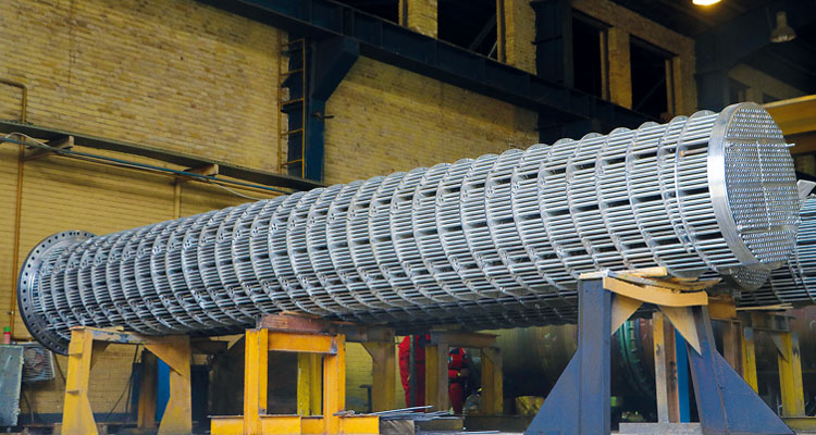
Shell and Tube Heat Exchanger is the most common of the various types of unfired heat transfer equipment. It is the only type which can be considered for large surface areas having pressure greater than 30 bar and temperatures greater than 260.A shell and tube exchanger consists of a number of tubes mounted inside a cylindrical shell. Two fluids can exchange heat, one fluid flows over the outside of the tubes while the second fluid flows through the tubes. The fluids can be single or two phase and can flow in a parallel or a cross/counter flow arrangement. The shell and tube exchanger consists of four major parts: Front Header: this is where the fluid enters the tube side of the exchanger. Rear Header: this is where the tube side fluid leaves the exchanger or where it is returned to the front header in exchangers with multiple passes. Tube bundle: this consists of the tubes, tube sheets, baffles and tie rods etc. to hold the bundle. Shell: this contains the tube bundle
The popularity of shell and tube exchangers has resulted in a standard nomenclature being developed for their designation and use by the Tubular Exchanger Manufactures Association, known as TEMA, which is intended to supplement the ASME Boiler and Pressure Vessel Code, Section VIII, Division 1.TEMA presents three mechanical standards which specify design, fabrication and materials of shell and tube heat exchangers as follow: Class R: petroleum and related processing applications. Class C: commercial and general process applications. Class B: chemical process service.
There are three types of shell and tube heat exchangers:
- Fixed tube sheet exchangers
- U-tube exchangers
- Floating header exchangers
Header and Shell Types:
- A-Type front header
- B-Type Front Header
- C-Type front header
- D-Type front header
- N-Type front header
- Y-Type front header
- E-Type shell
- F-Type shell
- G-Type shell
- H-Type shell
- J-Type shell
- K-Type shell
- X-Type shell
- L-Type rear header
- M-Type rear header
- N-Type rear header
- P-Type rear header
- S-Type rear header
- T-Type rear header
- U-tube
- W-Type rear header
The selection of tube diameter is a compromise taking into account the fouling nature of the fluids, the space available and the cost. Tubes of 19.05 and 25.4 mm outside diameter are the most widely used, but small units with clean fluids may use tubes as small as 6.35 mm outside diameter.The maximum tube length for removable bundle exchangers may be restricted to about 9 m. The maximum tube length for fixed tubesheet exchangers is less important but may be limited to about 15 m.The tubes are laid out in triangular or square patterns in the tube sheets. The square layouts are required where it is necessary to get at the tube surface for mechanical cleaning. The triangular arrangement allows more tubes in a given space. The tube pitch is the shortest center-to-center distance between tubes. The tube spacing is given by the tube pitch/tube diameter ratio, which is normally 1.25 or 1.33. Since a square layout is used for cleaning purposes, a minimum gap of 6.35 mm (0.25 in) is allowed between tubes.
Baffles are installed on the shell side to give a higher heat-transfer rate due to increased turbulence and to support the tubes thus reducing the chance of damage due to vibration. There are three baffle types, which support the tubes and promote flow across the tubes shows:
- Single Segmental
- Double Segmental
- Triple segmental Single segmental baffles are the most common, but where a design is governed by shell-side pressure loss, it may be reduced appreciably by resorting to double or triple segmental baffles. The center-to-center distance between baffles is called the baffle-pitch and this can be adjusted to vary the crossflow velocity. In practice the baffle pitch is not normally greater than a distance equal to the inside diameter of the shell or closer than a distance equal to one-fifth the diameter or 50.8 mm (2 in) whichever is greater. In order to allow the fluid to flow backwards and forwards across the tubes part of the baffle is cut away. The height of this part is expressed as a percentage of the shell diameter, is termed the baffle-cut.Typical baffle cuts are 15-40% for Single segmental baffles and 20-30% for double segmental baffles.The size of the baffle-cut needs to be considered along with the baffle pitch. It is normal to size the baffle-cut and baffle pitch to approximately equalize the velocities through the window and in crossflow, respectively. In shells of TEMA types G, H, K and X the shell-side fluid need not flow to and fro across the bundle, in which case cross-type baffles are not required. Full-circle baffles or support plates which are not cut away at all are used and every tube is supported at every baffle. In order to assemble the bundle there must be a reasonable clearance between the baffle and tube, but if the clearance is too large it may have an adverse effect on heat transfer and promote flow-induced vibration problems. Customary practice is to drill the hole 0.4-1.0 mm greater than the tube outside diameter, depending on service, tube size and baffle pitch.
This plate is about 6 mm thick, flat or curved, with dimensions greater than the nozzle bore.To protect the tubes below the shell-side inlet nozzle from damage due to solid particles or liquid droplets entrained in the shell-side fluid, an impingement plate may be required.
Tie rods and spacers hold the bundle and locate the baffles in their correct positions. Tie rods are screwed into the stationary tubesheet and extend the length of the bundle up to the last baffle. All the rods have spacer tubes fitted over them, each spacer being tube or pipe with an inside diameter greater than that of tie rod diameter, and a length equal to the required baffle spacing. Undesirable shell side leakage paths, such as the gaps due to pass partitions or gaps between bundle and shell, shall be blocked by tie rods and spacers.
- Extended surfaces Tubes can be finned on both the interior and exterior. This is maybe the oldest form of heat transfer enhancement. Finning is usually desirable when the fluid has a low heat transfer film coefficient.The fin not only increases the film coefficient with added turbulence but also increases the heat transfer surface area.The most common type is “low fin tubing” where typically the fins are 1.5 mm high at 19 fins per inch.
- Tube inserts Wire wound iinserts, turbulators, or static mixers are inserted intothe tube to promote turbulence. These devices are most effective for high viscosity fluids in a laminar flow regime. Inserts are used most often with liquid heat transfer and to promote boiling. Inserts are not usually effective for condensing in the tube and almost always increase pressure drop.
- Deforming for tubes Tube deformation appears corrugated, twisted, or spirally fluted. Therefore, twisted tubes promote heat transfer coefficient and turbulence and enhance boiling.
The thermal design of a shell and tube exchanger is an iterative process which is done using computer programs such as the Heat transfer and Fluid Flow Service (HTFS) or Heat Transfer Research Incorporated (HTRI). In order to calculate the heat transfer coefficients and pressure drops, initial decisions must be made on the sides the fluids, the front and rear header type, shell type, baffle type, tube diameter and tube layout. The tube length, shell diameter, baffle pitch and number of tube passes are also selected and these are the main items during each iteration in order to maximize the overall heat transfer within specified allowable pressure drops. The mechanical design of a shell and tube exchanger is done using computer programs such as PV Elite which provides information on items such as shell thickness, flange thickness,nozzle thickness, etc. but stresses should not exceed allowable stresses.